Would you like to make this site your homepage? It's fast and easy...
Yes, Please make this my home page!
Contact Breaker Point Gap and ignition
Timing Adjustment
Adjustment of the point gap and ignition timing should be made
for both R/H and L/H cylinder at one time. To adjust, proceed
as follows:
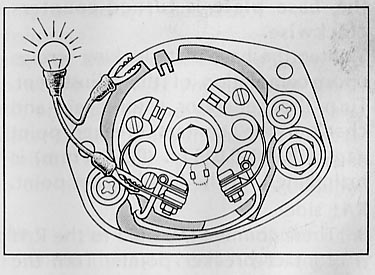
Contact Breaker Point Gap:
Turn the generator rotor counterclockwise and check the point
gap when it is maximum. The correct gap is 0.012-0.016 in.
(0.3-0.4 mm) for the L/H and R/H points. Then loosen the contact
breaker plate locking screws (5) when the point cam (1) is at
maximum lift and move the contact breaker point plate (4). Tighten
the locking screws when the correct gap is obtained. Adjust both
L/H and R/H points in the same manner. Recheck the gap after tightening
the locking screws.
NOTE: Wipe the contact breaker point surfaces with clean rag
if dirty.

Ignition Timing: Adjust the ignition timing upon completing
the adjustment of the contact breaker point gap. L/H side
- Turn the generator rotor (6) counterclockwise and align "LF"
mark (8) (on L/H cylinder) to timing mark (7). The ignition timing
is correct. if the L/H contact breaker point (2) starts opening.
To check the ignition timing, connect a 12V-3W bulb as shown
in the figure and observe the moment the bulb comes on (see figure
below)
- If the ignition timing is incorrect (either advanced or retarded),
align "LF" mark to the timing mark, loosen base plate
locking screws (10) and slowly turn base plate (11) until the
bulb comes on.

NOTE: The ignition timing will be advanced if the base
plate is turned clockwise; it will be retarded if the base plate
is turned counterclockwise.
Tighten the base plate locking screws upon completion of the
adjustment. Turn the generator rotor again and check if the contact
breaker point gap of 0.012-0.016 in. (0.3-0.4 mm) is maintained
for the L/H breaker point.
R/H side
- Then connect the bulb to the
R/H contact breaker point. Turn the generator rotor counterclockwise
180 degrees (1/2 turn) and align "F" mark (9) with
timing mark (7). If the bulb comes on when the marks are aligned,
the ignition timing is correct. If the ignition timing is incorrect,
loosen contact breaker base plate locking screws (12) and vary
the R/H point gap within the range of correct gap to adjust the
ignition timing.
- When the correct ignition timing is not obtained even if
the R/H point gap is varied within the range of correct gap,
a readjustment is required in conjunction with the ignition timing
of the L/H cylinder.
When this is the case, proceed as follows:
- Move the R/H contact breaker plate in the direction of adjusting
the ignition timing within the range where the R/H point gap
of 0.0120.016 in. (0.3-0.4 mm) is maintained, and tighten
the plate lock screws. (reduce the point gap if the ignition
timing is advanced and increase the gap if it is retarded.) Then
loosen the base plate locking screws and turn the base plate
until the correct ignition timing is obtained for the R/H cylinder.
- Move the L/H contact breaker plate in the direction of adjusting
the ignition timing within the range where the L/H correct point
gap is maintained.

Repeat the operation outlines in pars. 1) and 2) until the
correct ignition timing is obtained for both L/H and R/H cylinders.
If the correct ignition timing is not obtained for either L/H
or R/H cylinder within the point gap range of correct gap, replace
the contact breaker point assembly with a new one and make a
readjustment.
NOTE:
- Make sure to turn the rotor counterclockwise. Do not reverse
the rotor even when it is overturned.
- It is advisable that L/H and R/H contact point gap be
identical in setting.
HOME CB 450
K5 information CB
450 K5 Manual: Table of Contents